Crack Management In Vintage Pipelines

Interpreting In-Line Inspection Data to Help Eliminate Unnecessary Digs
In-line inspection (ILI) tools are a rapidly evolving technology for ensuring the integrity of pipelines that are susceptible to crack anomalies. Several vendors offer ultrasonic crack-detection (UTCD) tools that can be used to detect and size cracks in liquid pipelines, while electromagnetic acoustic transducer (EMAT) tools are growing in popularity for gas pipelines. These developing tool technologies provide operators with significant amounts of data on the extent and severity of cracks and crack-like flaws. While in many cases this information is critical to making informed pipeline-integrity decisions, it is important to remember that having more data is not always beneficial.
Given that crack-detection tools are an emerging technology, it is not surprising that many operators are confronted with unexpected results from their ILI runs, especially in vintage pipelines. Crack-detection tools may be particularly susceptible to returning false identifications as a result of manufacturing anomalies that can produce signals similar to those from actual cracks. Many vintage pipeline systems have manufacturing anomalies such as laminations or slivers in the pipe body that do not affect the integrity of the pipeline, but can be detected during inspection. Understanding whether a crack-detection tool is identifying a legitimate threat is critical to helping operators manage their integrity programs while minimizing unnecessary digs.
Background
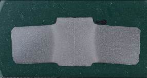
Many older pipelines in the United States were constructed from pipe material with seam welds manufactured via flash welding (FW) or low-frequency electric resistance welding (LF-ERW) techniques. A cross-section of an example flash weld on a vintage pipe manufactured by A.O. Smith is shown in Figure 1. Both FW and LF-ERW vintage seam welds have known issues that can be detrimental to the overall integrity of a pipeline. Cold welds, lack of fusion, stitching, under-trim, and selective seam corrosion (SSC) have all been observed in vintage FW and LF-ERW seam types. The presence of these types of issues has resulted in the use of the term “seam susceptibility” when referring to this category of seam welds. Fortunately, seam susceptibility concerns were greatly reduced in the US after pipeline manufacturers switched to high-frequency ERW construction techniques in the 1960s.

In recent years, the use of crack-detection tools to manage seam susceptibility issues has increased. While an operator’s primary concern may be the seam weld, crack-detection tools can detect a variety of other anomalies as well. The detection of a defect that may have been missed by a metal-loss tool (such as stress corrosion cracking) is certainly beneficial to the operator; however, in many cases, crack-detection tools may mistakenly identify pre-existing manufacturing flaws in vintage pipelines as crack-like defects, resulting in unnecessary analyses and excavations.
Assessing Probability of Identification
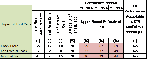
Improper identification of flaws can lead to unnecessary digs for operators and may result in an ILI tool run being disqualified. ILI tool performance is normally quantified in terms of statistical measures. Tool specifications provide the probability of identification (POI) and probability of detection (POD) for various types of features the tool can detect. For many tools, the expected POI is stated as 90% or greater for cracks or seam weld flaws. Sizing of flaws is often expressed as a certainty; for instance, 80% of the time the crack depth will be sized within ±1 mm.
In vintage pipeline steels, it is possible that a crack-detection tool may incorrectly identify mill flaws as cracks or notch-like features. Since these mill flaws (such as slivers, scratches, and laminations) have typically survived at least one hydrotest, they likely do not pose an integrity concern to the operator.
Stress Engineering Services (SES) can assist operators seeking to qualify a tool run by identifying dig locations that will maximize the number of independent validation samples. In addition, SES can assist with processing dig data to determine whether a tool met its stated specification in terms of POI, POD, and/or sizing. An example POI assessment is shown in Table 1.

Vintage Pipeline Steels
As mentioned, vintage pipeline steels (generally considered as those manufactured before 1970) may exhibit a variety of manufacturing-related anomalies that are not considered an integrity threat to the pipeline. Figure 2 shows an example of a sliver-type flaw. These flaws, which can occur during the rolling process, may be several feet long; however, a metallurgical mount of this example sliver-type flaw shows that it is oriented parallel to the pipe surface and is very shallow (< 1 mm). These types of flaws, which may be common in vintage steels, typically register an ILI signal similar to that from a crack with a depth greater than the sliver depth. If burst calculations are performed based on the reported (incorrect) flaw geometries, the resultant survival pressures may be overly conservative. SES has demonstrated how a grinding procedure can be used to confirm the orientation and depth of these types of flaws (Figure 3). By lightly grinding perpendicular to the axis of the pipe and using MP, the orientation of the flaw can be clearly determined.


Demonstrating Pipeline Integrity through Full-Scale Testing
SES also assists operators by demonstrating the fitness for service of these manufacturing flaws via full-scale destructive testing. In instances where multiple features are called, a few select features may be removed for full-scale testing. The flaws can be instrumented prior to testing to monitor their growth.
In the case shown in Figure 4, sliver flaws covered a large portion of the pipe joint. NDT performed in the field indicated depths exceeding 40% of the pipe wall and the corresponding predicted burst pressures resulted in unnecessary pressure reductions and ultimately removal of the pipe. Full-scale testing later demonstrated that the flaws had no detrimental effect on the pressure integrity of the pipe, with measured burst pressures exceeding those predicted using specified minimum pipe properties. Ultimately, the test failure occurred outside of the flaw area in an adjacent pup piece that was free from flaws.

Conclusions
The emergence of crack-detection tools has provided a great benefit to operators managing threats posed by cracks. However, effective interpretation of crack-detection tool data is essential to maintain the integrity of the pipeline and reduce unnecessary digs. SES has successfully used statistical analyses to evaluate whether crack-detection tools perform according to their specifications. In addition to providing confidence in the ILI data; SES has helped operators understand how to properly assess various manufacturing flaws when encountered in the field. Metallurgical analysis and full-scale testing can be used to characterize features that have been identified by ILI and quantify their impact on the overall performance of the pipeline.

Brent Vyvial, PE – Principal, Houston Office
Brent Vyvial has been a member of the Stress Engineering Services family since 2006, and was recently promoted to the position of Midstream Practice Lead. He has extensive experience in full-scale testing and analysis of pipeline anomalies as well as pipeline repair methods. He is also a registered Professional Engineer in the State of Texas.


Leave a Comment
You must Register or Login to post a comment.