An Inside Look at Force Calibration
For force measurement, the process of calibration is the comparison of applied forces indicated by a measurement system under test to a calibration standard. The traceability of the standard used defines the resulting range and accuracy of the system being tested. For example, the ISO-13679 standard (“Procedures for testing Casing and Tubing Connections”) addresses measurement range and accuracy by specifying that the calibration standard must be traceable to the National Institute for Science and Technology (NIST), accurate to within 1% (of reading) and that the calibrated range must encompass the loads to be used in the test program. Upcoming updates to API 5C5 will address tolerances for load control in a test, implying the need to increase accuracy and reduce sources of error. For example the following is being required: “During hold periods, the axial frame load shall be maintained between the target axial frame load ±0.5 % or ±22 kN (5 kips), whichever is greater.”
Measurement traceability begins at the International System of Units (SI) and is defined by the accuracy at each “link in the chain” between the SI standards and the measurement system being used for a test. In the United States, the connection with SI starts at NIST. For force measurement, NIST maintains six deadweight machines ranging from 505 lb to 1,000,000 lb capacity. NIST states that the “relative standard uncertainty of applied force is 0.0005%” for these machines. In the range of 1,000,001 lb to 12,000,000 lb (compression only), calibrations are performed in a testing machine using load cells calibrated in a deadweight machine.
At Stress Engineering Services, we use Class A load cells calibrated by Morehouse Instrument Company (York, PA) to calibrate our OCTG load frames. Morehouse uses deadweight machines for force calibrations up to 120,000 lb with certification traceable to NIST. Load cells (also certified to NIST) are used for forces above 120,000 lb to a capacity of 2,250,000 lb compression (1,125,000 lb in tension).
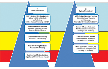
Figure 1: Traceability from SI to Stress Engineering Services
The traceability chain between SES and the SI Standards is illustrated in Figure 1. Accepted calibration practices dictates a minimum of a 4:1 ration in accuracy between each step it the traceability chain. ISO 13679 specifies that the machine errors observed in calibration be less than 1% (of reading); however, it does not address tolerances in the traceability chain or how many “links” in the traceability are allowable. The measurement system calibration should include the error from the 4:1 accuracy ratio or the calculated error from all the traceability links separating the calibration standard from NIST. In fact, other standards such as ISO 17025 (and ASTM) are specific with respect to acceptable traceability and how the uncertainty at each step affects the overall results of a machine calibration. For a calibration to meet ISO 17025, the uncertainty at each “link” in the traceability chain must be quantified with the contributing components identified. This approach yields a true indication of the accuracy of measurements.
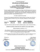
Figure 2: Calibration Certificate for Morehouse Load Cell
As documented in Figure 2, Morehouse calibrated one of its 1000 kip load cells in tension and compression. Three runs of data were recorded, with the cell rotated between each data run to identify any sensitivity associated with the load cell and the press used for the calibration. The “Class A” lower limit for this system is determined as a function of the standard deviation from the data fit and the system resolution as follows:
Lower Limit = 400 * (Standard Deviation) * (Average Force / Deflection) * 2.4
The factor of 400 incorporates the 4:1 ratio between steps in traceability, while the 2.4 factor is an empirical constant used in ASTM E74. Note that the lower limit is different for each mode of calibration (tension and compression).
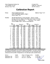
Figure 3: Calibration report for a Stress Engineering Load Frame
Several factors govern the lowest traceable forces in the calibrated range of a machine. First the calibration standard must be able to provide traceability (with the number of links from NIST) at the desired minimums and the errors associated with the links and the measuring system. The machine must have sufficient resolution such that the indications provided can discern 1% of the reading at the lower bound of the loading range. The machine indications must also be able to demonstrate repeatability over the entire range, particularly in the lowest readings.
For SES’s 800 kip machine (Figure 3), two different calibration standards with overlapping capacities are used to provide traceability from 50 to 900 kip tension and 30 to 600 kips compression. This range may vary between annual calibrations depending on the results at the lowest loads. In August 2016, the tension calibration 40 kip data point was not sufficiently repeatable to meet the 1% specification. This point is represented in the data and highlighted to emphasize that it is for reference only and not part of the certified range.
The frame and standard load cells (Figure 4) are configured so that the set-up can be readily changed between the two standards; they are interchanged several times during both the tension and compression calibration. The systems are exercised to capacity prior to recording data, particularly if the set-up has been changed such as interchanging the standard cells. The ambient temperature is monitored throughout the calibration, and a displacement transducer is used to monitor movement in the frame as the load is cycled.
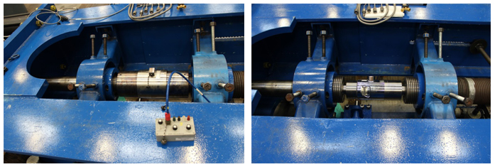
Figure 4: Set-up of standard cells for calibrating load frame: 1,000 kip cell (eft) and 300 kip cell (right)
In addition to the errors associated with the calibration chain between SES and NIST, there are other potential sources of error that can dramatically affect the results of a calibration:
- Incorrectly setting the zero indication on a machine will have a detrimental effect on all the subsequent data displayed and recorded by the system. On most calibration systems there is no “double-check” for how zero is set.
- ASTM standard practice E4 directly addresses the calibration of an instrument outside the machine with which it is typically used.
- Mechanical factors have been documented as producing calibration errors:
- Loading through threads versus surfaces
- Mounting considerations
- Non-parallelism, flatness, stiffness and surface hardness
- Alignment and bending
- Electrical considerations:
- Changing or substituting indicators or indication systems
- Modifications or damage to signal cables. The length of a signal cable can reduce the apparent output of a system by increasing the lead resistances.
- Power fluctuations and power or signal grounding.
When a calibration certificate is reviewed, the following questions will help users ensure confidence in the accuracy of the calibration:
1. Was the calibration performed with both increasing and decreasing loads?
2. How many runs were completed? A minimum of two runs are typically performed.
3. Does the stated error include the accumulated error from each of the links separating the end user from NIST?
4. Was the measuring system calibrated as a system, including the electronics that will be used during the load measuring?
5. If the calibration was performed using a load bar separated by multiple links from NIST, what errors are introduced?
Using a calibrated bar introduces additional error as it is a link further away from the standard. The electronics used with the bar may not be the same used for its original calibration introducing further unaccounted errors. This is why a calibration bar is used for checking the calibration (see ISO 13679/API 5C5) and not for performing calibration.
** This article appears in the 2017 issue of Stress Talk **


Roy Nash – Associate II, Waller Office
Andreas Katsounas, PE – Principal, Houston Office
Roy has been in the business of performing traceable calibration and load measurement services for over 32 years. Andreas’ expertise is in combined load and fatigue testing of threaded tubular connectors as well as the use of non-linear finite element analyses for the evaluation of structural and mechanical components.


Leave a Comment
You must Register or Login to post a comment.